Login & Main Interface

Login

No account or password required. Launch the software and it goes straight to the main interface.
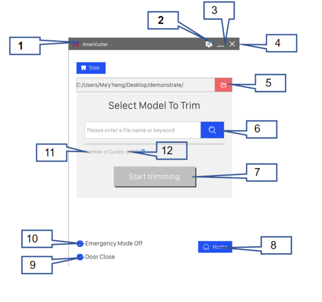
Main Interface Overview

Screenshot
Screenshot

Device Connection & Power-On Check

Before starting any cutting operation, complete the following checks:

  • Connect the device to a stable power supply.
  • Confirm the USB data cable between device and computer is firmly connected.
  • Check that the emergency stop switch is not triggered and is in normal standby.
  • Confirm the safety door photoelectric switch is working normally.

Homing (Return to Zero)

Press the [Home] button at the bottom of the main interface. The device will automatically execute the axis homing sequence. Once homing is complete, you may proceed with the next operation.

Basic Parameter Settings

Calibration — Overview

Calibration eliminates installation deviations, compensates for positioning data lost during device relocation, computer replacement, or software reinstallation, and ensures cutting accuracy while reducing material waste.

Two calibration modes are available: Manual and Automatic.

Manual Calibration

When to use Manual Calibration:

  • First-time device installation and setup
  • Computer replacement
  • Software reinstallation causing registry positioning data loss
  • Accuracy correction after abnormal automatic calibration
Prerequisite: Prerequisites (all must be confirmed):
  • Device connected to power and powered on
  • USB cable connection is normal
  • Emergency stop switch is in the off position
  • Safety door is fully closed
  • Calibration rod is installed on the spindle
  • Calibration disc is seated correctly

Operation Steps:

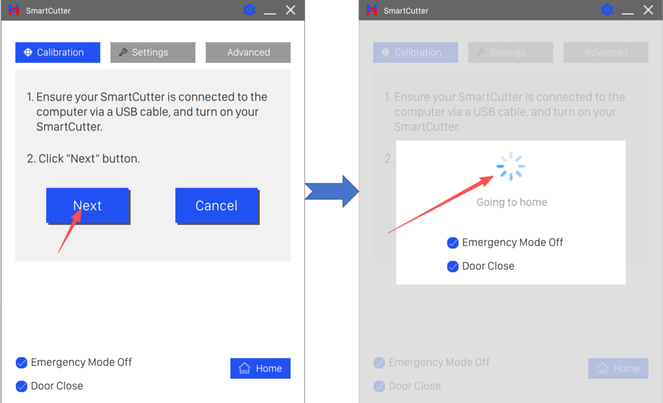
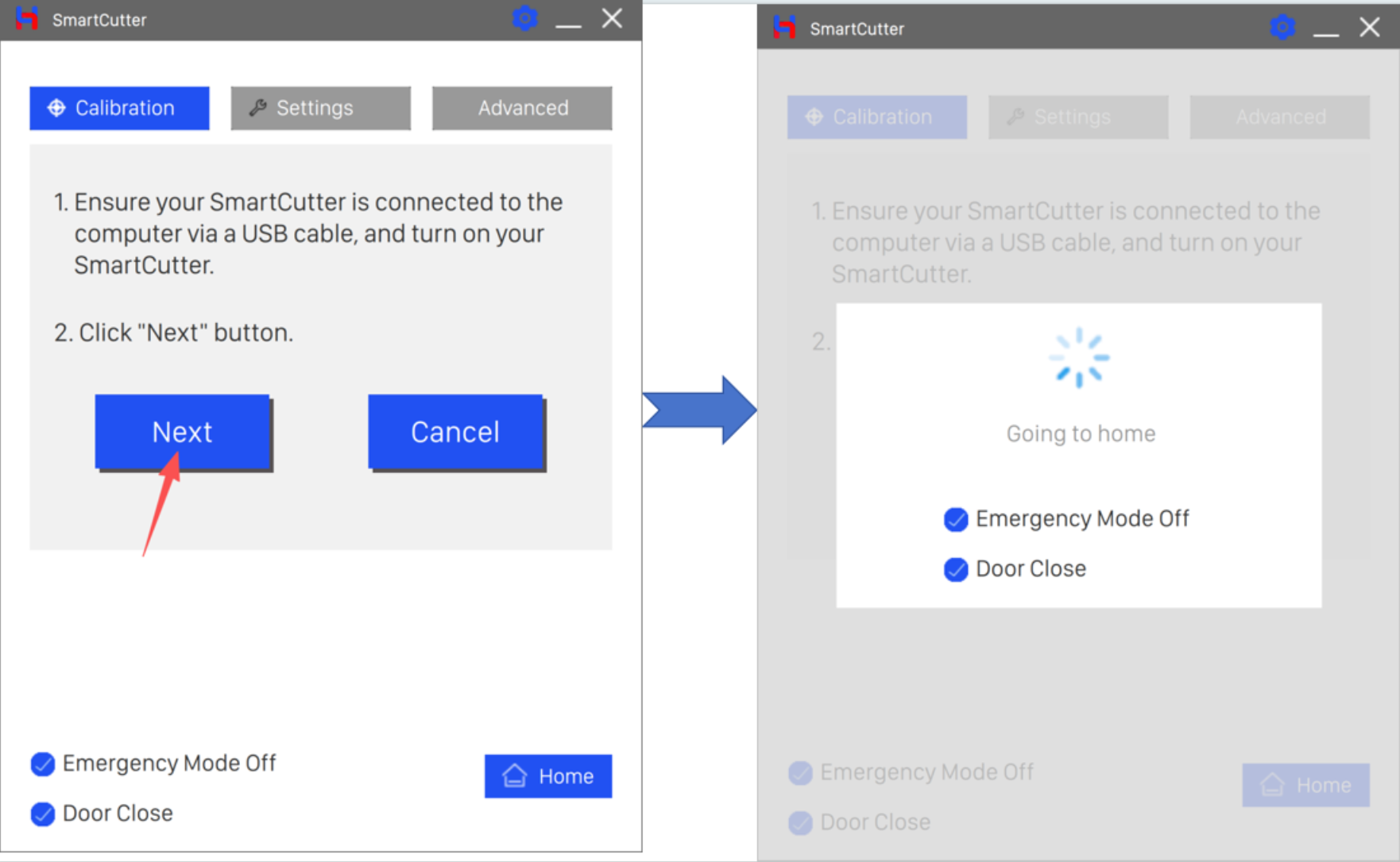
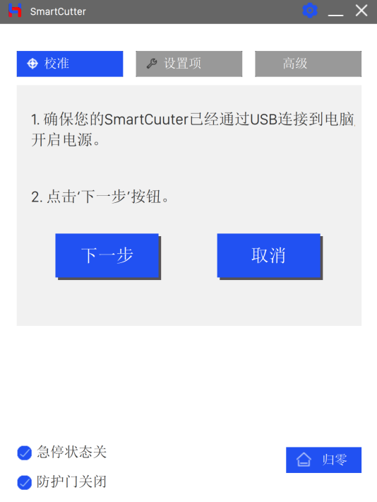
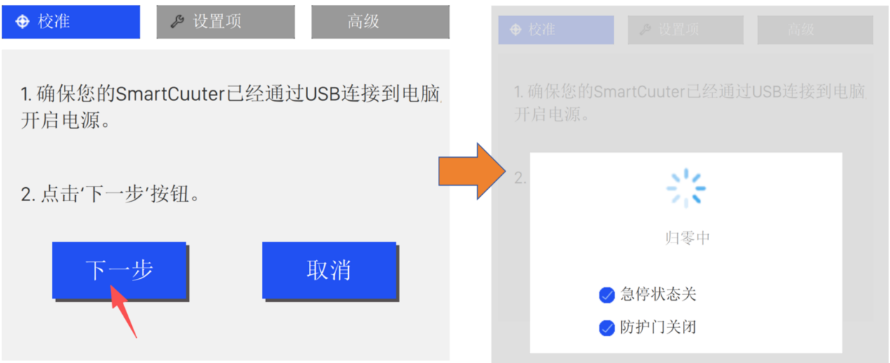
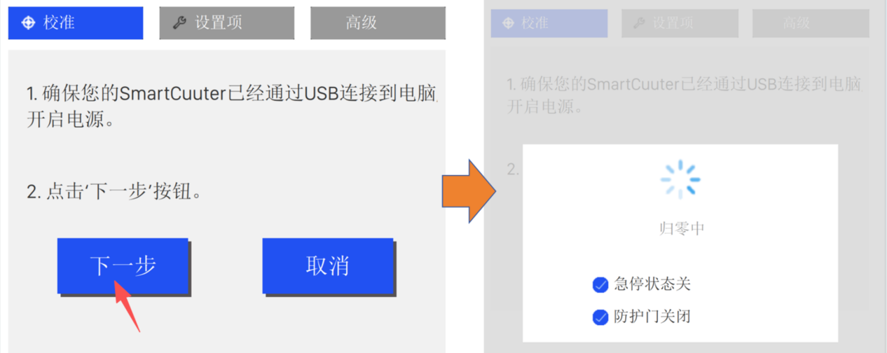
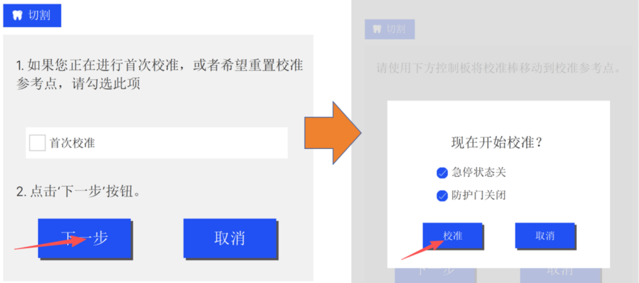
  1. Confirm all prerequisites on the calibration screen, then click [Next]. The device will automatically execute the homing sequence.
Screenshot
Screenshot
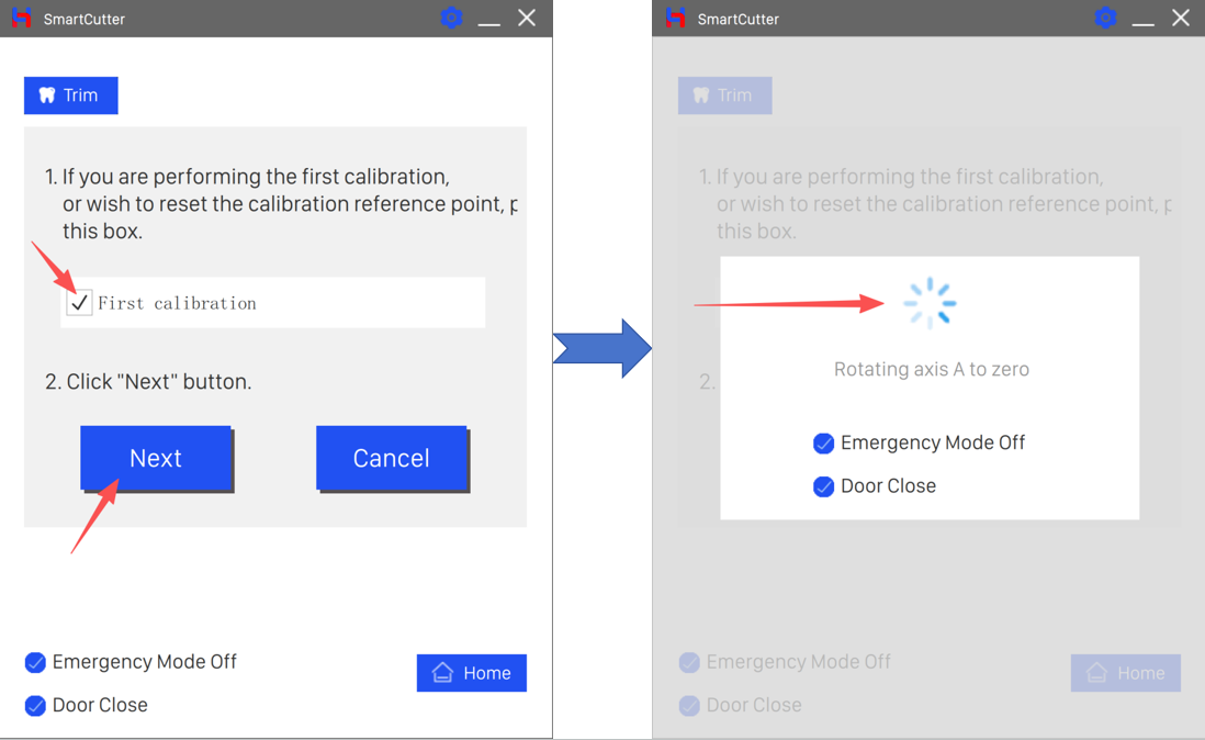
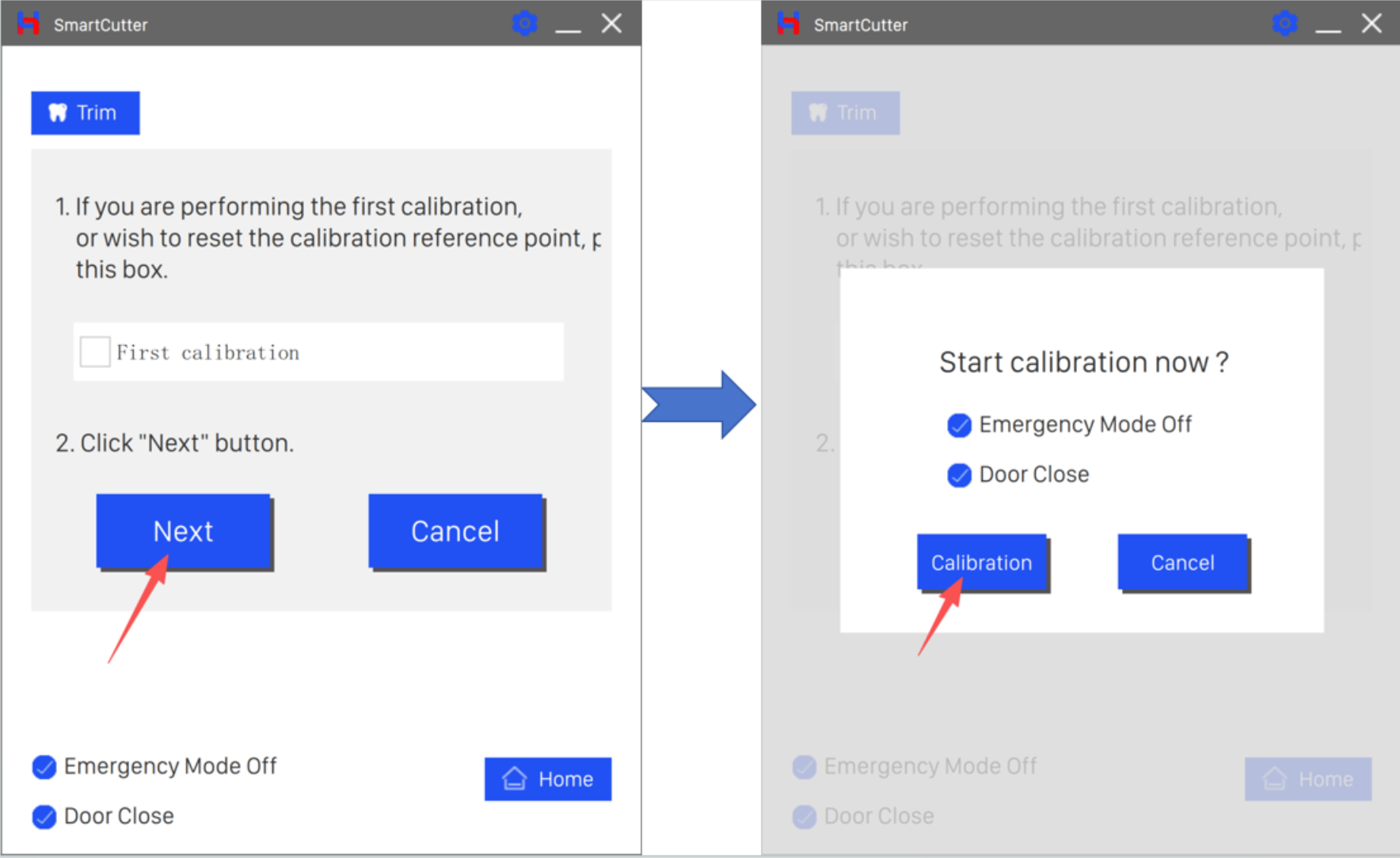
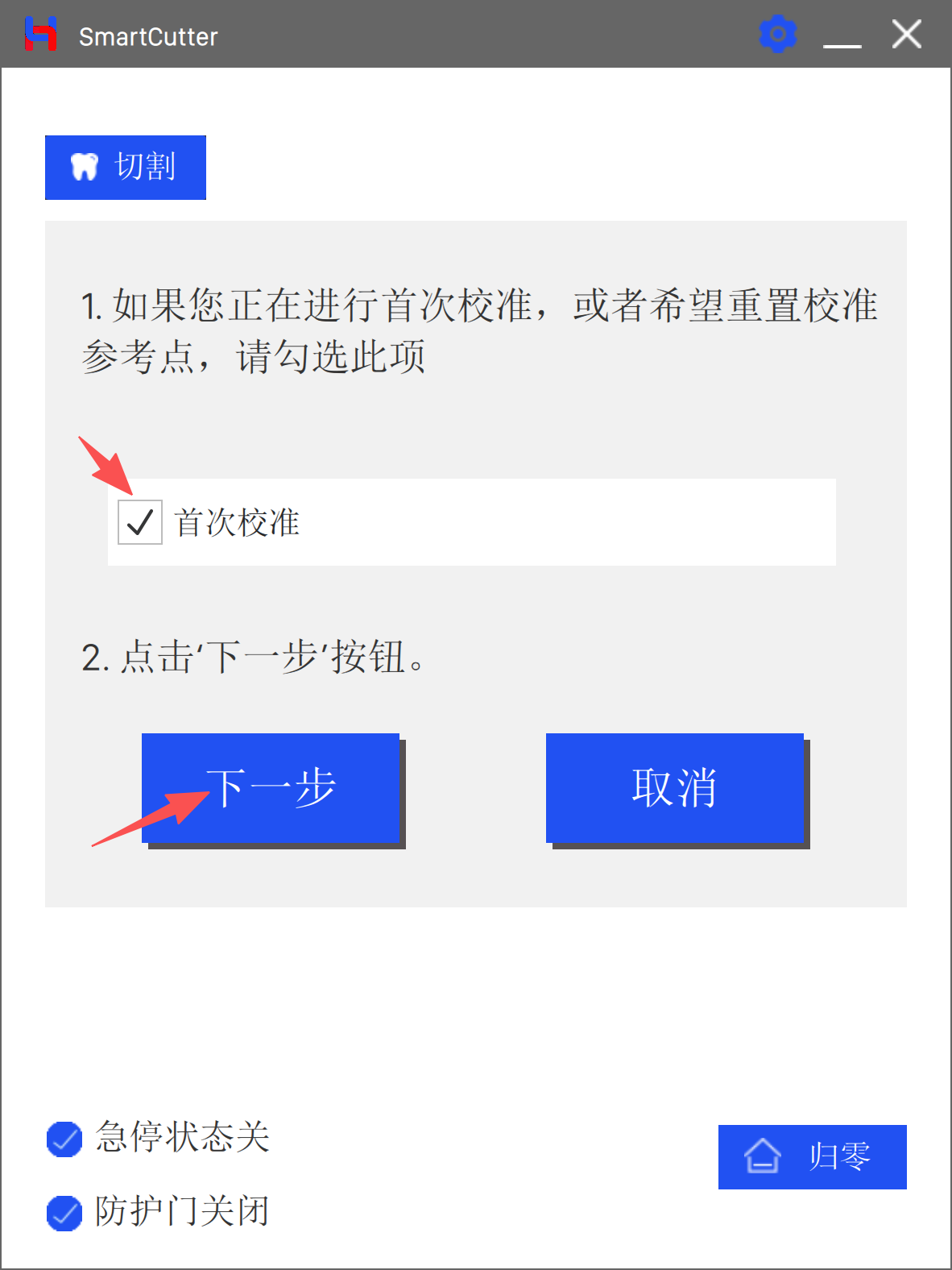
  1. After homing is complete, select First Calibration, then click [Next] again.
Screenshot
Screenshot
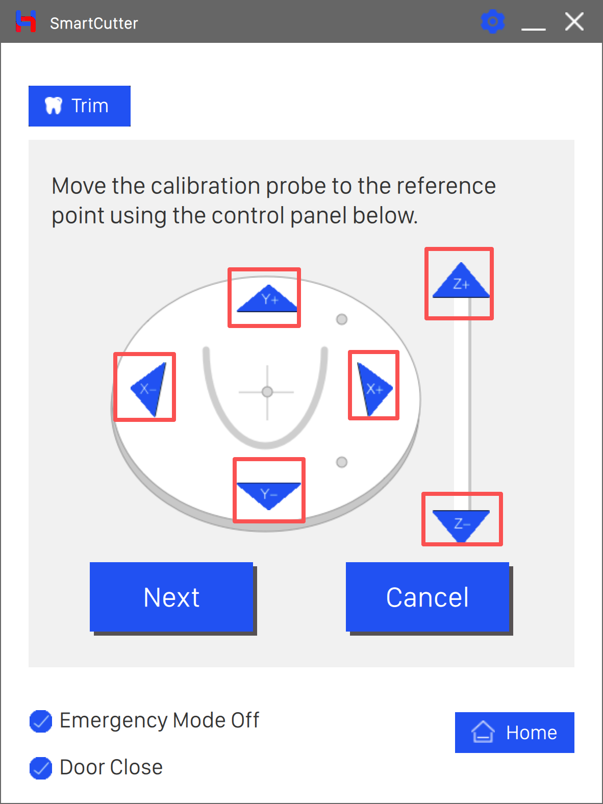
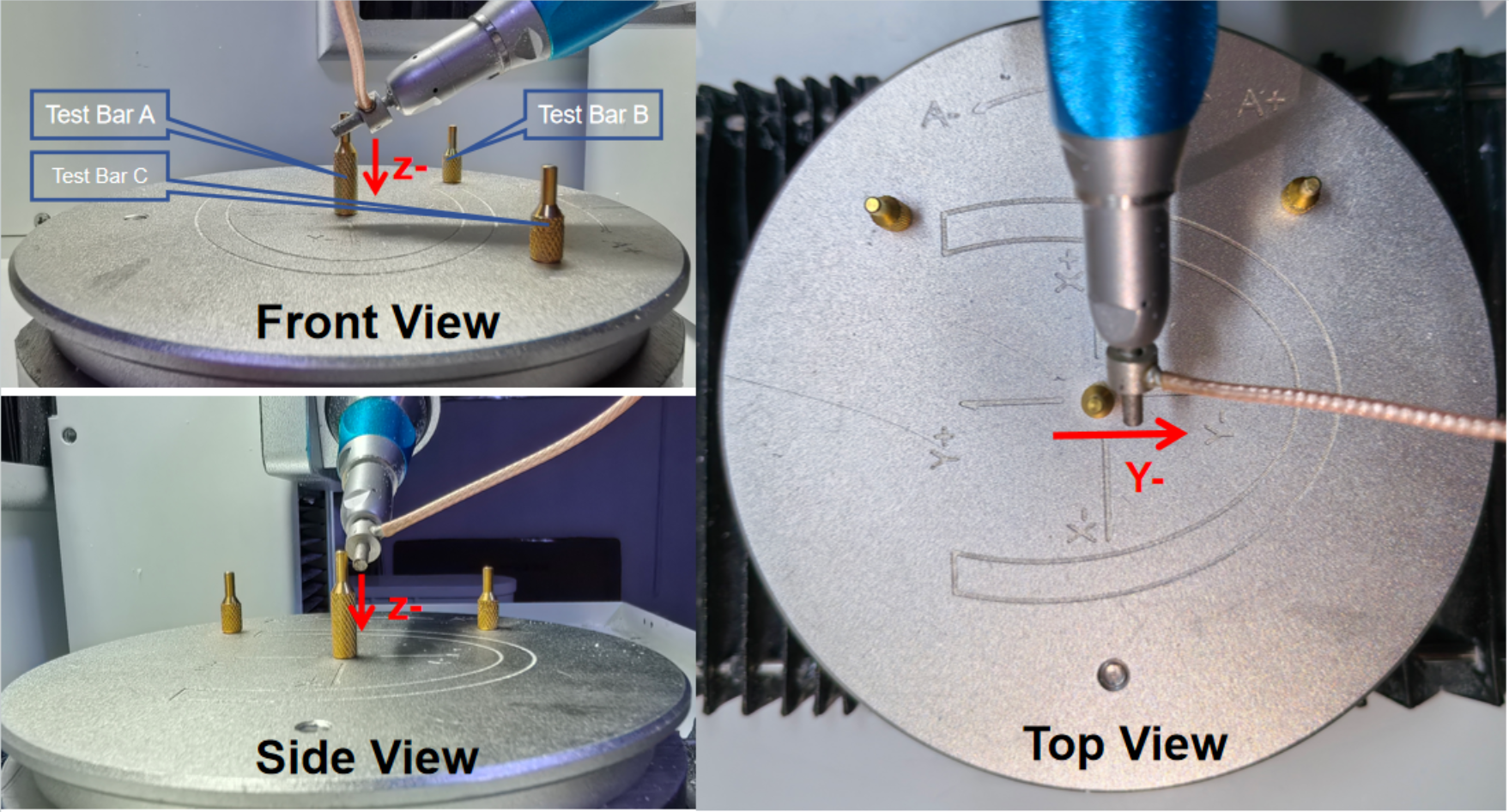
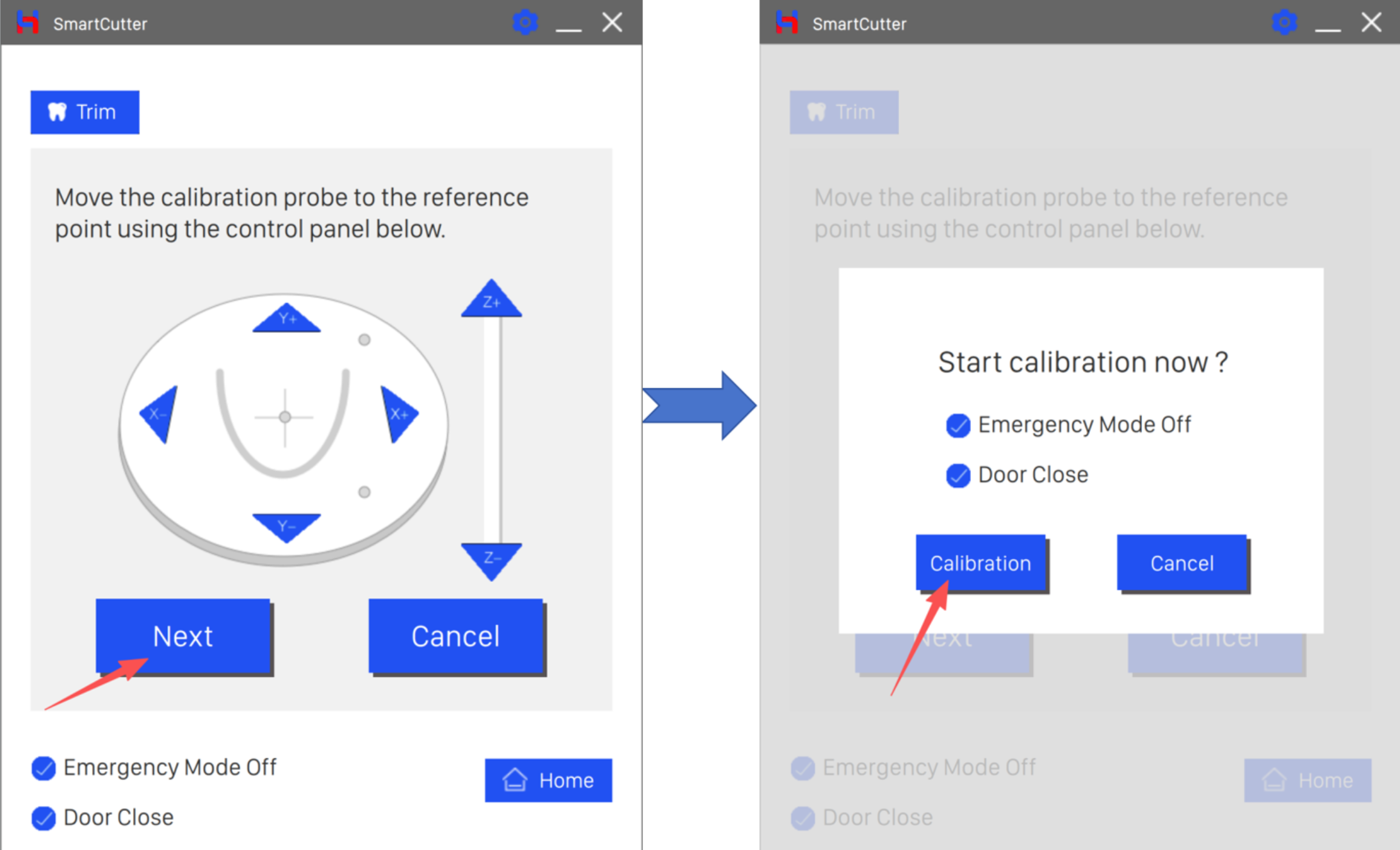
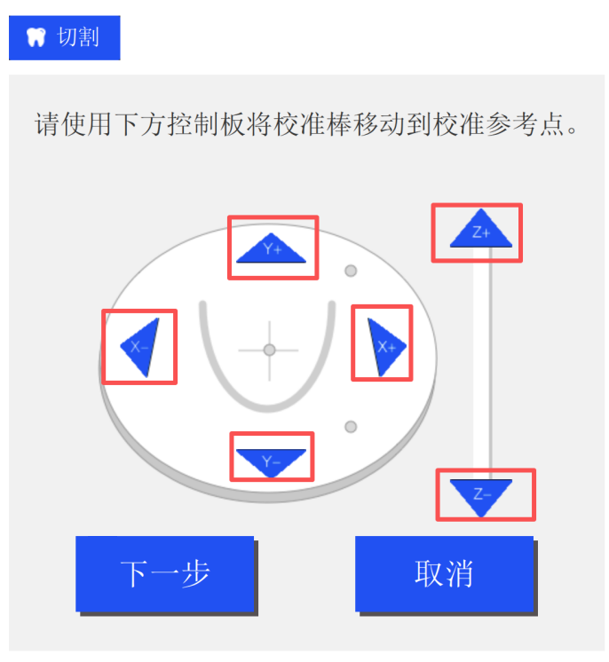
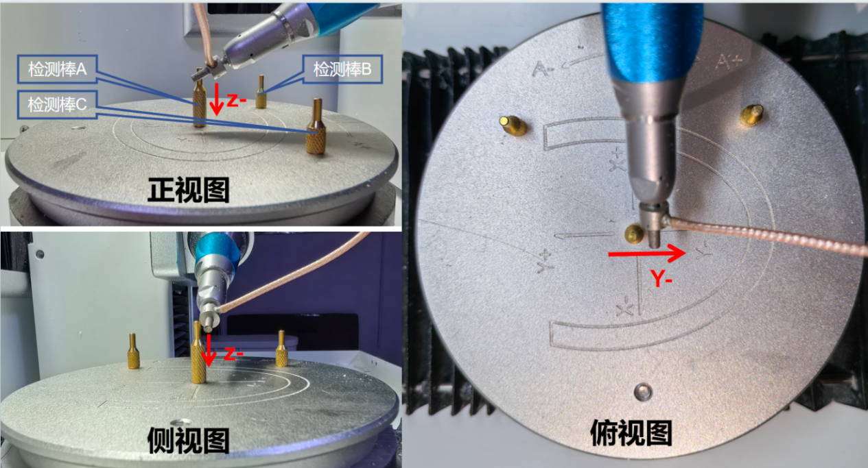
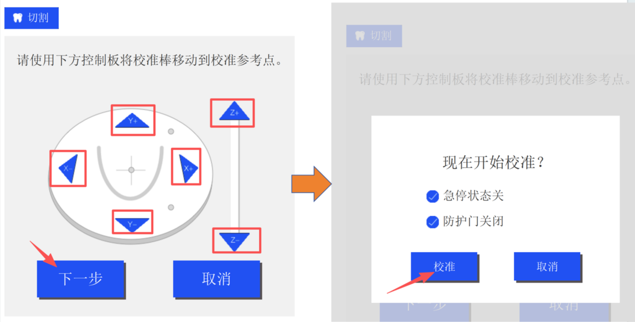
  1. Use the X+/X−/Y+/Y−/Z+/Z− jog buttons to precisely position the calibration rod to the reference point:
  • X direction: approximately −2 mm
  • Y direction: approximately −2 mm
  • Z direction: the highest point of the detection rod, approximately 3 mm downward
  1. The spindle calibration reference point is where the spindle rod and the disc's calibration center cross — they must NOT make contact.
Screenshot
Screenshot
Screenshot
Screenshot
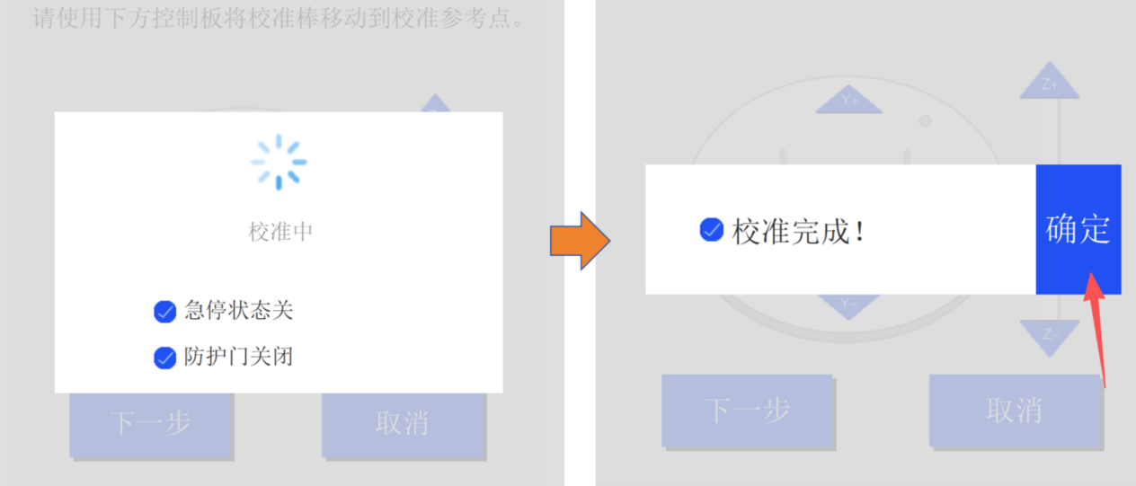
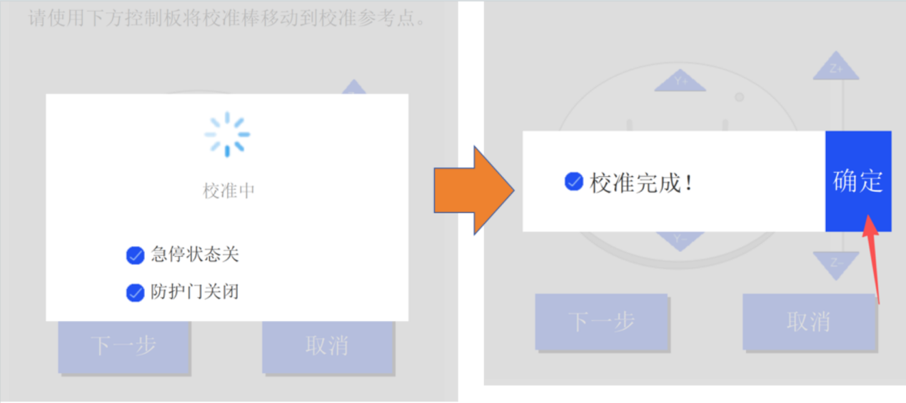
  1. Once positioned correctly, click [Next] to start the automatic calibration process.
Screenshot
Screenshot
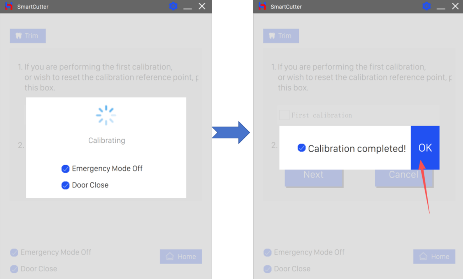
  1. After calibration finishes, click [OK].
Screenshot
Screenshot

Automatic Calibration

When to use:

Routine pre-production precision calibration before normal production runs.

Prerequisite: Prerequisites:

Same as manual calibration (see section 4.2).

Operation Steps:
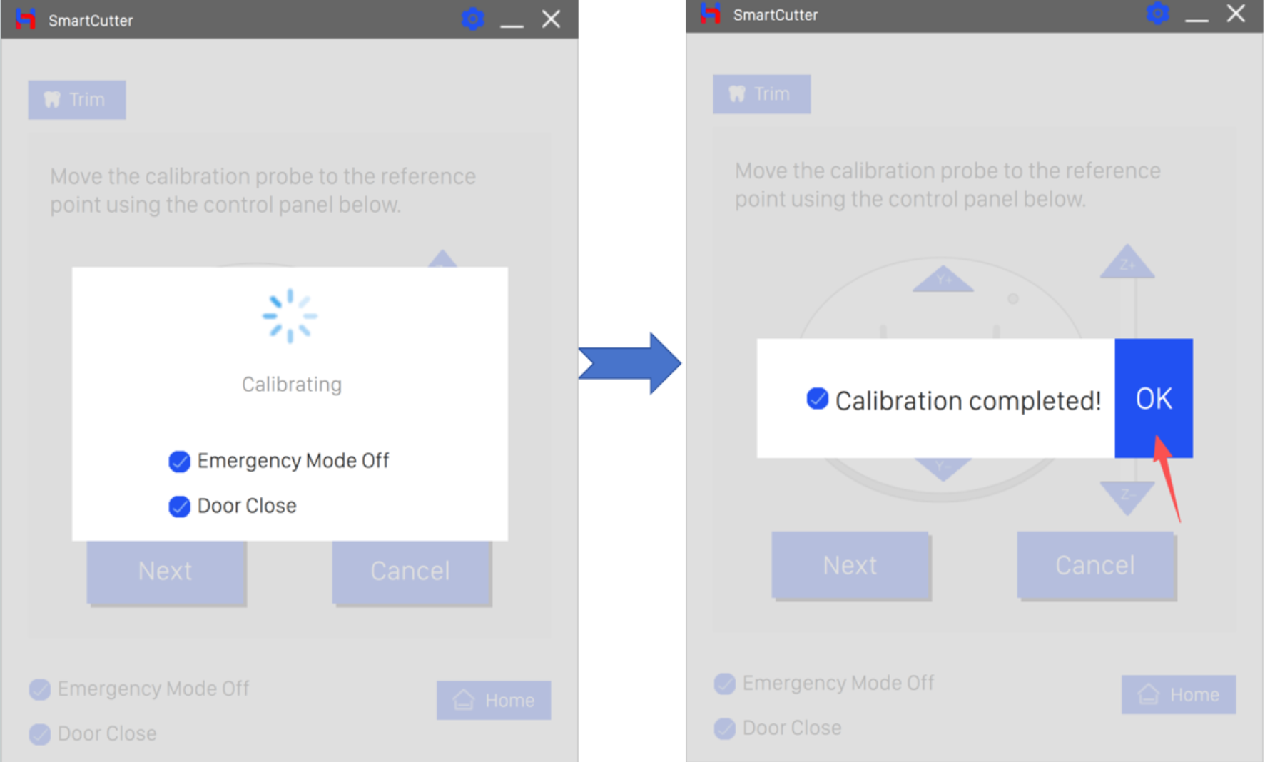
  1. Confirm all prerequisites on the calibration screen, then click [Next]. The device executes the homing sequence.
Screenshot
Screenshot
  1. After homing is complete, click [Next] again.Click [Next] to start the automatic calibration process. The spindle completes the calibration automatically.
Screenshot
Screenshot
  1. After calibration finishes, click [OK].
Screenshot
Screenshot

Settings — Cut Depth, Height, Speed & Language

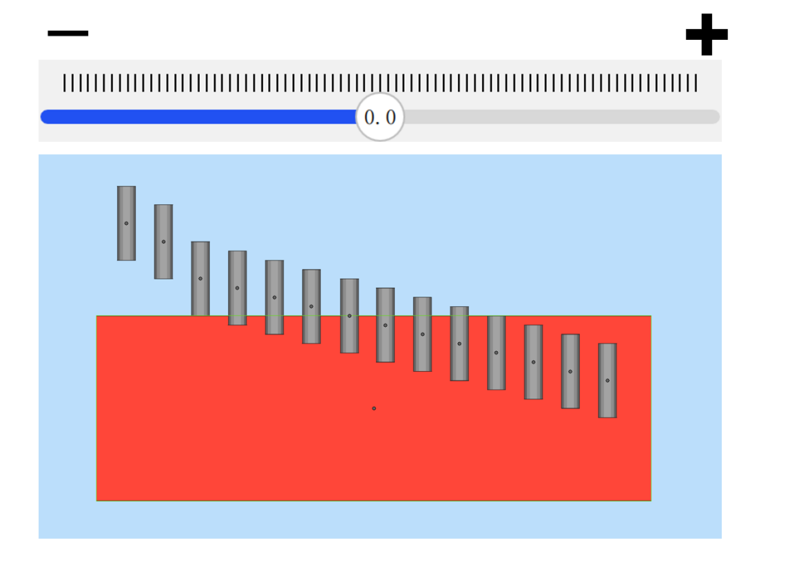
Cut Depth

Controls how deep the blade cuts into the model.
Screenshot
Screenshot

Adjust according to the thickness of the material being cut.

Height (Z-axis Offset)

Vertical offset of the blade relative to the original cutting line.
Screenshot
Screenshot

Speed

Cutting travel speed as a percentage. Adjustable range: 50%–150%. Default: 100%.

Higher speed = higher efficiency. Setting speed too high causes blade overheating, debris buildup, and risk of blade breakage.

Language

Switch between Chinese and English interface display. After selecting, click [Apply] and restart the software.

Advanced Settings

Executing a Cutting Job

Step 1 — Select the folder

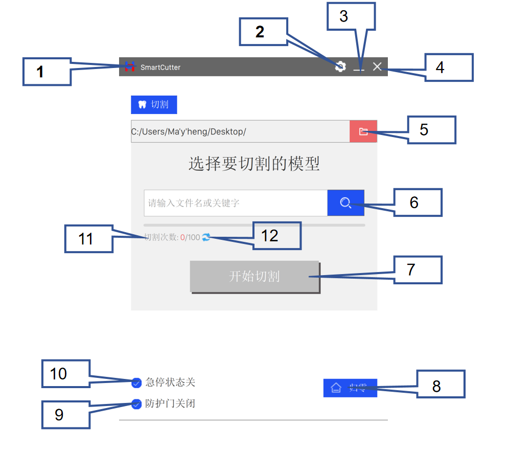
Click the red folder icon (marker 5, top-right of main interface) and navigate to the folder containing your cutting files. Select the target folder and confirm.

Screenshot
Screenshot

Step 2 — Select the file

Click the blue magnifying glass icon (marker 6) and choose the model cutting line file. Click Open to confirm.

Screenshot
Screenshot

Step 3 — Preview and confirm

The software jumps to the preview screen, showing the selected cutting line and the matched model file. Verify that the cutting line and model are correct. Optionally enable the two-pass cutting function, then click Confirm at the bottom.

Screenshot
Screenshot

Step 4 — Start cutting

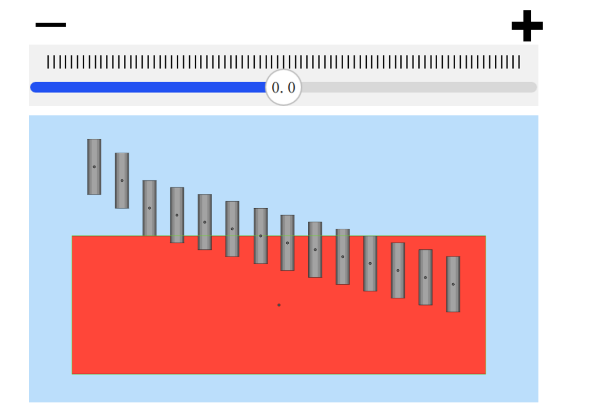
Click the Start Cutting button. A confirmation dialog will appear. The software switches to the cutting simulation screen. After the process completes, a completion dialog will pop up. Click OK — job is done.

Screenshot
Screenshot
Screenshot
Screenshot

Troubleshooting

Hardware Issues

Software Issues

Other Common Issues

Quick Reference — Simplified Workflow

Screenshot
Screenshot

SmartCutter User Manual • SC-002 Dental Aligner Cutting Machine

© 2026 Shaanxi Hongfan Zhihui Electromechanical Technology Co., Ltd. | www.hongfanzhihui.com | Contact: info@hongfanzhihui.com